Click her to go to 'Figures/Overheads' section.
Click here to return to course outline.
The object of the exercise is to setup an empty Snowlake database, modify the STATI and LITHO tables of the database by adding and rearranging fields in these tables, create a USER to UTM transformation algorithm, and input two ASCII comma delimited data files into the STATI and LITHO tables.
In following these instructions do not enter the quotes symbol () unless explicitly told to do so.
FOR COMPUTERS OPERATING IN DOS - see Appendix A below
FOR COMPUTERS OPERATING IN NT4 WITH AUTOCAD MAP RELEASE 2
Copy the folder Snowemp
in Earthnt\public\505\Fieldlog to a Fieldlog folder in your area
in Earthnt\users, rename the Snowemp folder to 'flyourinitials', and map
a network drive to 'Users'.
OR
Make a directory 'flyourinitials'
in d:\acadmap2\fieldlog, e.g. d:\acadmap2\fieldlog\flwrc, copy snowemp.exe
and the files 200av3n.txt and 200bv3n.txt in folder d:\acadmap2\Snowemp
to this directory, and expand snowemp.exe by double clicking the file name.
(Check with the instructor as to which method to use; if the snowemp.exe
zip file fails to expand copy the Snowemp folder from Earthnt\public\505\Fieldlog,
the snowemp.exe file at this location having already been unzipped.)
Load Autocad, click Fieldlog in the Autocad map menu bar, click Load Fieldlog, click 'fl-setup', and Project Setup. Select the project to be used during the exercise if the instructor has already set up the project for you, or create a new project by clicking NEW and entering a project name (left box; schema), the path to the project folder in the Users area (catalog), and DB3 as the database type. Then click the Insert button. You may have already carried out this procedure in the previous Snowlake exercise. (Note: if there are projects already listed, your new project must be located in the same Fieldlog directory. In other words, if a project is listed as having a path d:\acadmap2\fieldlog\flwrc, your project must also include the path segment d:\acadmap2\fieldlog ) If you dont understand this procedure, request the help of the instructor. This operation will establish the database 'schema' used by Autocad map.
In the Fieldlog menu 'fl-setup', select 'fl-logon' , and click the OK button if the name of your database appears in the 'Database Name' scroll down selection box. If not, scroll to your database name, click the name and then click OK.
Once Fieldlog and the
database have been loaded, it will be necessary to carry out the following
procedures:
1) setup the map projections,
2) add fields and/or modify the existing fields in the Tables, and set
the field parameters,
and 3) import the ASCII formatted data.
1) - SETUP THE DATABASE
Select 'fl-Setup' followed by 'Map Setup'. In the 'Map Projection' scroll-down list select USER as the Map Projection.
(It is important that the Map Projection chosen correspond to the projection of the map to be drawn or that is already drawn on the monitor screen; that is, if the map on the screen is a UTM NAD27 map, the projection should be cited as such. If the Projection is a particular user projection then it will be necessary to carry out a user projection setup as described below. Note also that many of the selection boxes will already have inserted what appears to be a default value. However, in the case that you are using the DOS version of FLOG3, it will be necessary to select (confirm) the entry in the box by clicking on it.)
Enter values of 1 for the Symbol: and Text Height:, 90 for the North Angle:, and Y for the Clockwise angle: Click the OK button.
The
projection setup
The
projection setup involves defining the projection to be used in your project.
Again select 'fl-setup',
click 'Projection Setup' to retrieve the 'Projection
Setup' window and in the 'Map Projection' scroll down list scroll
to and click on Snowlake to load this projection as a template for your
projection. Change the name Snowlake in the NAME box of Projection
setup to flyourinitials, change the 'Units' to
meters from degrees, and click the INSERT
button to create a Projection named flyourinitials. Since you will
be adding data to a User grid map rather than an UTM map, return to 'Map
Setup ' and scroll and select flyourinitials as the projection.
Your
project can be setup such that the program will automatically convert the
data you input into other projections or datums. In particular, as in the
present project 'snowemp', you may want to convert your 'User' projection
to a standard UTM projection, and perhaps also to Lat-Long. The STATI table
already includes the USER coordinate fields Gridx, Gridx, Gridz, and the
UTM fields UTMx, UTMy, and UTMz.
From fl-setup select 'Transformation
Setup', and in the Transformation Setup menu click NEW, and type flyourinitials
to Utm Zone 17 NAD27 in the Name box. In the 'From Projection'
and 'To Projection' boxes scroll and select flyourinitials and Utm Zone
17 NAD27, respectively. Click the INSERT
button. Click the POINTS box and in the 'Transform
Points Setup' menu box enter the User values '0' and '0' in the
flyourinitials X and Y boxes, and 147863 and 1477863 as the corresponding
UTM values in the Utm Zone 17 NAD27 X and Y boxes. Click the INSERT button.
Click NEW and repeat the operation entering values of 200 and 200 as
the flyourinitials X and Y values, and 148063 and 1478063 as the Utm
Zone 17 NAD27 X and Y values. Agian click INSERT, and then EXIT the Transformation
Points Setup menu.
Click the New box in the 'Transformation Setup' menu and repeat the exact reverse operation for a Utm Zone 17 NAD27 to flyourinitials transformation.
In both cases, the transformation will be orthogonal to orthogonal. (In other circumstances the Transformation may be from orthogonal to rotated orthogonal, or even UTM to rotated and distorted orthogonal USER, and vice versa.) Exit the Transformation Setup menu, and click the Save Fieldlog setup option.
At
this point you will need to tell Fieldlog which projections you wish to
have calculated and added to the database.
Select 'Table
Setup' and the Project flyourinitials, click Table and then STATI.
To record which fields are to be used as coordinate fields [VERY
IMPORTANT], click the 'Points' box
to retrieve the POINT SETUP menu. Delete any selections
already made by clicking on them and then clicking the delete button.
Select UTM 17 NAD27 in the Projection box, STATYPE in the Symbol
box, and UTMX, UTMY, and UTMZ in the X, Y, and Z boxes, respectively.
Click insert such that:
UTMX
UTMY UTMZ UTM 17 NAD27 STATYPE appear
in the upper box.
Repeat this operation,
selecting flyourinitials in the Projection box, STATYPE in the Symbol
box, and GRIDX, GRIDY, and GRIDZ in the X, Y, and Z boxes, respectively.
Click insert such that:
GRIDX
GRIDY GRIDZ FLYOURINITIALS STATYPE
appears
in the top line of the upper box. Make sure this latter line appears
above the UTMX, etc, line. Exit and click the Save Fieldlog setup option.
[NOTE: if you have already placed a LONGITUDE, LATITUDE, and ELEVATION field after the UTM fields in the STATI Table (see the following section on how to add and move fields), where each of these fields is set to have dimensions of 12 spaces and 6 decimals (e.g. -84.345765), you would need to add a Lat-Long option to POINTS by selecting GEOGRAPHIC NAD27 in the Projection box, STATYPE in the Symbol box, and LONGITUDE, LATITUDE, and ELEVATION in the X, Y, and Z boxes, respectively.]
2) - ADDING
AND/OR MODIFYING FIELDS
Now youare going to add additional
fields to the LITHCODE table and rearrange some of the fields in the STATI
table.
Adding Fields
In the 'Table
Setup' menu click the "Table" button, select the "LITHO" table, and
then click the "Column" button. Click "NEW", type LITHCODE in the field
entry box, and click the box containing the field names. Click the MOVE
button and move the LITHCODE field above the ROCKTYPE field. Click
the SETUP button to verify that the field has been registered as a CHARACTER
field.
With the LITHCODE field selected, click the save button, and then click the PALETTE button to retrieve the 'Symbol setup' menu. Set the LAYER on which the field is to reside as LITHCODE, as well as the options for the SIZE (1), COLOUR (red), and OFFSET of the LITHCODE text symbol (offset Y -1; that is 1 unit to the left of the outcrop symbol STATYPE).
Repeat this operation and ADD a METALS field, and MOVE the METALS field above the CLRWEATH field, SAVE the change, and use PALETTE to modify the parameters of the METALS (size 1; offset x 1, y 1). Again repeat the operation to add a Z (or "ROCKNUM") numeric field after the METALS field.
Re-arranging Fields
Similarly, in the "STATI" table
use MOVE to rearrange the fields in the relative order: GRIDX, GRIDY,
GRIDZ, UTMX, UTMY, UTMZ, STATNUM, STATYPE, TRAVNUM. Check whether the value
in the STATNUM field is 'character' or 'Numeric'. Save the changes and
use PALETTE to modify the parameters of the STATYPE field (change from
shape to block; LAYER = statype, SIZE = 0.2; all OFFSETS = 0), the
STATNUM field (LAYER = statnum, SIZE 1, offset x 1; y 1), and the TRAVNUM
field (LAYER = travnum, SIZE 1, offset x -1.
Be
careful, do not look in the STATI table for the new fields you previously
added to the LITHO table!
[If you wish to have an entry for the coordinates as Lat-Longs, as well as USER and UTM, add LONGITUDE, LATITUDE, and ELEVATION fields (in that order) before the STATNUM field, and in the SETUP menu, retrieved by clicking the SETUP button in the Table Setup menu, set the LONGITUDE and LATITUDE fields to NUMERIC with a field length of 12 and number of decimal places 6. Then return to the POINTS SETUP menu (click the POINTS box) to enter the conversion parameters, as described above, and such that the order from top to bottom is GRID, UTM, LATLONG.]
Exit the Table Setup menu, Save (important) the changes to the Fieldlog Tables, and exit the fl-Setup menu.
Test the Database
Choose fl-add
to test the addition of a data point into the STATI table (stationnum -
me1; traverse - 1), and plot the point to the screen (as in the SNOWLAKE
exercise). Using fl-query, create a new query
as STATI, get the STATI database (use STATI.STATNUM > 0 as the search criteria),
and delete the me1 record from the STATI table. Exit fl-query, go to
fl-setup -> Table setup, select STATI as the
table, and click the PURGE button to remove the deleted record from the
database. Click EXIT, then 'Save Fieldlog setup', and finally EXIT again.
If you don't understand these instructions, ask the instructor for help.
3) -IMPORT
To import the data set c:\flyourinitials\200av3n.txt"
into the STATI table, select 'fl-import' in the
Fieldlog 'fl-setup' menu. Click in order: PROJECT, TEXTFILE, FILE, and
FILENAME (200av3.dat) to be imported.
Click IMPORT,
and in the 'Import Text File' window click
the Table name STATI, the APPEND button, enter a comma (,) into the Column
Delineation box, a quote symbol () in the Text Delineation box, and select
flyourinitials in the Projection box - if you are using the DOS version
of FLOG, it is IMPORTANT to click this latter item even although flyourinitials
may be shown as the default selection; if it is not selected FLOG will
not prompt you to do so.
Finally (BE CAREFULL!),
select the fields to be imported in the Import Fields box, i.e. only those
fields GRIDX, GRIDY, STATNUM, STATYPE, TRAVNUM in 200av3.dat. Click the
import button to initiate the import.
Repeat this procedure to import the data in c:\flyourinitials\200bv3.txt" into the LITHO table, selecting the fields - STATNUM, LITHCODE, ROCKTYPE, METALS and Z (or ROCKNUM), in the Import fields box.
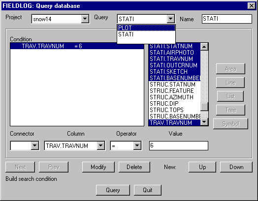
4) - QUERY
and PLOT
Once the data is correctly imported you will
need to plot the data via the Query function.
Save SetUp and return to the
Fieldlog 'fl-setup' menu. Select 'fl-Query' and
create a Query macro (e.g. name it PLOTT in the name box) to plot the LITHO.LITHCODE
and LITHO.METALS fields in the LITHO table, and the STATI.STATYPE, STATI.STATNUM,
STAT.TRAVNUM, STATI.GRIDX, and STATI.GRIDY fields, in the STATI table,
to the screen. To select the fields in the scroll down list
of fields, simply click on each field sequentially while holding the CTRL
key down. HOWEVER, after having set up the PLOTT macro, click the Query
button to run Query, thereby registering the PLOTT macro, but do
NOT procede with the plot option. Rather, quit Query, return to 'fl-setup',
click the 'Save Fieldlog Setup' button (i.e. the Query macro PLOTT), and
re-run the PLOTT macro in 'fl-query', choosing Map
as the plot option. In the Plot Options
window select the fields to plot (click
while holding down the CTRL key to make several selections, e.g.
Stati.Statnum, Stati.Statype to plot the outcrop location and the outcrop
number. Note that the coordinate values in STATI that are used to
plot the data must correspond with the Projection chosen in PROJECTION
SETUP, or , if a drawing has already been loaded by Autocad, with the Projection
used by that drawing. Also note that at this stage it is also possible
to alter the character of the output symbols (size, colour, etc) by selecting
the relevant field and clicking the Palette button to access the 'Symbol
Setup' window.
If the values in the
STATI.STATION field are entered as character strings of the form '001',
'021', '100', etc, the search condition 'STATI.STATNUM > ' used in Query
must be written in the form e.g. STATI.STATNUM > 021, and not STATI.STATUM
> 21.
5) - UTM
to LAT-LONG conversion
If you are importing
coordinate data as UTM's, and wish Fieldlog to carry out a UTM to
LAT-LONG conversion during the import, make sure that the coordinates in
the file being imported are in the order Easting x, Northing y, Statnum,Outcrop
(where Outcrop is the statype outcrop symbol field), and that:
1) in the STATI table
the fields are organized as UTMX, UTMY, UTMZ, LONG, LAT, ELEV, STATNUM,
and STATYPE;
2) add a Lat-Long option
to the 'Point Setup' setup in 'Table
Setup' (click the POINTS button) by selecting GEOGRAPHIC NAD27 in
the Projection box, STATYPE in the Symbol box, and LONG, LAT,
and ELEV in the X, Y, and Z boxes, respectively.
Once the data has been imported, Query the data and Plot as TXT, selecting the output fields as UTMX, UTMY, LAT, LONG, STATNUM, but first remove the UTM and Lat-Long projections from the projections list in 'Point Setup', leaving only a reference to the GridX-GridY projection.
6) - LAT-LONG
to UTM conversion
In the file being imported
the lat-long fields should be in the order LAT, LONG, but in Fieldlog the
coordinate fields in STATI should be in the order LONG (=X), LAT (=Y).
The rearrangement is done automatically by Fieldlog.
If a coordinate conversion is also being carried out, e.g. to Lambert Conformal Conical, set up and name the relevant Lambert projection, add a Lambert lat-long option to POINTS, and add the Lambert coordinate fields to STATI in the order Lambertlongitude, Lambertlatitude, Lambertelevation. Note: to set a condition involving several criterion, e.g. stati.statnum => 010 and <= 020, or stati.statnum => 010 and lith.metals = Au, set the first condition and click the MODIFY button; click the DOWN button; select AND in the connection box, set the second criterion, and click the MODIFY button again.
Appendix
A
FOR COMPUTERS OPERATING IN DOS
Make a subdirectory c:\flyourinitials by typing
md flyourinitials, where yourinitials really means the initials of
your name, not yourinitials, e.g. md flwrc.
Change to c:\flyourinitials
with the command cd flyourinitials, e.g. cd flwrc.
Copy the sample Fieldlog
file to this directory with the command copy c:\snowemp\snowemp.exe.
Type snowemp and press
the ENTER key to expand the snowemp files.
Delete snowemp.exe from the
flyourinitials directory with the command del snowemp.exe.
Copy the files c:\flog3\200av3n.txt"
and c:\flog3\200bv3n.txt" to the c:\flyourinitials directory withe the
command copy c:\flog3\200*.txt" where:
200av3.txt contains the comma delimited fields: XCOORD, YCOORD, STATNUM,
STATYPE, TRAVNUM e.g. 12,47,1,outcrop,1.
and 200bv3.txt the fields:STATNUM,LITHCODE,
ROCKTYPE, METALS, Z, e.g. 1,s, sandstone, Au, 3. If using autocad
version 12, enter the relevant set statements in the autoexec.bat and
the c:\acad\support\fieldlog.prj files according to the following instructions.
THE FOLLOWING IS IMPORTANT
- BE CAREFUL
Use the DOS Edit command to
place the statement set flyourinitials=c:\flyourinitials (e.g. set flwrc=c:\flwrc)
in the Autocad 2 (and Autocad 1 if it exists) menu sections of the autoexec.bat
file using the command edit c:\autoexec.bat) [If you dont know how to
use EDIT, request help from the instructor.].
Use the DOS Edit command
to place the statement flyourinitials=c:\flyourinitials,dBase3 (e.g.
flwrc=c:\flwrc,dBase3) in the c:\acad\support\fieldlog.prj file with the
command edit c:\acad\support\fieldlog.prj).
LOAD FIELDLOG
Run Autocad by typing acadtb
ENTER, load Fieldlog, and choose fl-logon in the Fieldlog menu. In
the Connect to Database dialogue box select flyourinitials.
REBOOT THE COMPUTER TO
REGISTER THE CHANGES IN THE AUTOEXEC.BAT FILE.
W.R. Church
Click fl-add in the Fieldlog menu; select STATI as the table in the Table drop down list, and enter a station number in 'STATNUM', a Traverse number in 'TRAVNUM', and optionally an outcrop number. Make sure the Plot check box is checked, and then click the Enter Data button. Place a STATYPE outcrop symbol onto the screen map by clicking the relevant location on the screen. (Note: if the angular offset has not been specified in Table setup, you may be requred to click THREE times, once to locate the symbol, twice after having interactively rotated the symbol, and a third time after having interactively placed the station number.) You will be returned to the 'Fieldlog: Add to Table' window with the option to enter a new station. Note that the 'STATNUM' and 'BASENUMBER' numbers will have been advanced by one. To place oriented structural symbols adjacent to the STATYPE symbol, select 'STRUC' as the table in the Table drop down list. The 'STATNUM' number will revert to that of the previously entered station but the 'BASENUMBER' will remain advanced by one. Click FEATURE and then the SYMBOL button, and select the symbol to be plotted, e.g. the subed symbol for bedding. Press the ENTER key to insert the data into the relevant field. Enter the data for the Azimuth and dip and
RETURN TO: