Understanding Map Projections and Grid referencing systems
Which Map is Best? - Projections for World Maps, 1986, 14 p., Special Publication
No. 1, Committee on Map Projections of the American Cartographic Association
(ISBN 0-9613459-1-8). (Not in Library)
Choosing a World Map -
Attributes, Distortions, Classes, Aspects, 1988, 15 p., Special Publication
No. 2, Committee on Map Projections of the American Cartographic Association
(ISBN 0-9613459-2-6).
Matching the Map Projection
to the Need, 1991, 30 p., Special Publication No. 3, Committee on Map Projections
of the American Cartographic Association (OSBN 09613459-5-0).
Snyder, J.P. 1984, Map
Projections used by the U.S. Geological Survey, Washington: U.S. Geological
Survey Bulletion 1532, 313p. (Call # US1 IN2 82B32; TAY govt 28 day).
Peter Richardus and Ron.
K. Adler, 1972, Map projections for geodesists, cartographers and
geographers. North-Holland Pub. Co., Amsterdam. ( Call #
GA110.R52, DBW stack 28DAY)
Snyder, P.J., 1984, Map
Projections - A working manual. US Geological Survey Professional Paper.
US Dpt. of the Interior 1395,100 p. (Call # US1 IN47 84P95
TAY govt 28DAY; US1 IN47 84P95 DBW govt 14DAY)
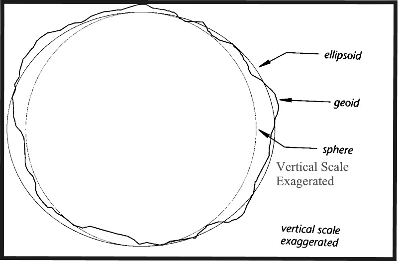
Geodesy
is concerned with the area and shape of the Earth, and in particular the
definition of a reference Earth shape known as the Geoid.
The Geoid is
an equipotential surface of gravity, ellipsoidal (oblate spheroid) in shape
because of the counter-gravity centrifugal forces generated by the spin
of the Earth about its N-S axis, and highly irregular because of the variability
in composition (density) of the Earth beneath each point on the Geoid (note:
the irregularities are not coincident with those exhibited by the Earth's
surface). The ellipsoid
model of the Earth attempts to define its shape in terms of a smooth ellipsoid,
and the use of satellite measurments have led to the development of the
WGS-84 (World Geodectic System) ellipsoid as the best ellipsoidal representation
of the Geoid. The maximum difference between the Geoid and the WGS-84 ellipsoid
is 1 in 100000 (100 metres). Ellipsoids have also been constructed
for individual continents and countries because different ellipsoids give
better fits to the Geoid at different locations, e.g. the Clarke 1866 ellipsoid
for the United States.
The
Geoid and Ellipsoid
The Ellipsoid information, an initial location
(origin), an initial azimuth (the direction of north), and the distance
between the Geoid and the Ellipsoid at the initial location defines a permanent
reference surface known as a 'Datum'. For example, the NAD-27 datum
(North American Datum , 1927 ) is based on the latitude and longitude of
Red Falls, Iowa, whereas the WGS-84 ( the World Geodetic Systems 1984 datum)
is based on measurements made from space, beyond the effects of local variations
in gravity. Each datum embodies its own concept of latitude and longitude,
and at any given locality, changing the datum may change a coordinate reading
by several hundred metres, as in the case of Sudbury. When giving a coordinate
location it is therefore always necessary to also give the datum being
used. Datums are a concern of surveyors.
Geodetic (geographic) coordinates are given in
terms of latitudinal and longitudinal degrees measured relative to the
equator and either east or west of the prime meridian running through Greenwich,
England, respectively.
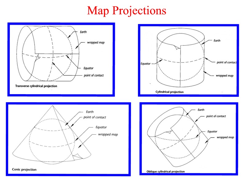
Map projection involves the transformation of
a 3-dimensional form into a 2-dimensional plane; they record the curved
surface of the Earth on a flat display. They may be cylindrical, conical
or azimuthal (planar). This is the field of cartography.
Cylindrical
and Conical Map Projections
As illustrated in the previous link, a cylindrical
projection can be realized by wrapping a sheet of paper around
the globe, in the form of a cylinder, projecting the geographical features
onto the paper, and then unrolling the paper as a flat sheet. Note that
the great circle of contact with the cylinder is the equator, and that
the lines of latitude and longitude projected along normals to the cylinder
will draw as an orthogonal graticule (grid) with the lines of longitude
equally spaced but the lines of latitude unequally spaced. Although
the shape of a large area is distorted, small areas are displayed relatively
accurately . The maps are said to be conformal.
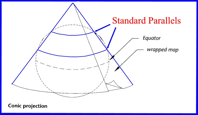
A conical
projection is generated in the same way but with the paper wrapped
as a cone such that the conical surface intersects the globe as a tangential
line of latitude, or, more usually, passes
shallowly through the globe between two small circles or latitudes
known as standard parallels (the secant case).
Standard parallels. Lines
of latitude and longitude would in this case appear on the flattened sheet
as a fan-shaped graticule, and all features lying on the concentric circles
of intersection would be undistorted. The most common conical projection
is the Lambert Conformal Conic Projection.
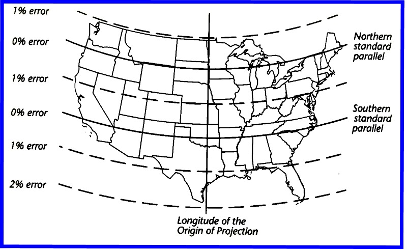
Lambert
Projection
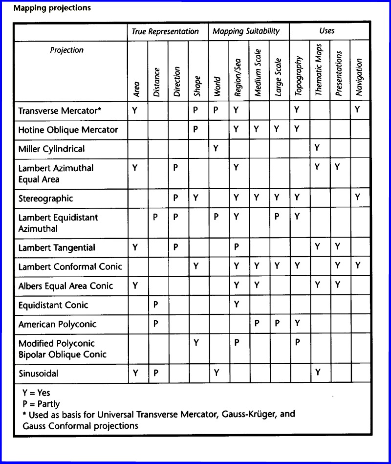
Map projections inevitably introduce distortions
of direction, area and shape into a map, and the projection to be selected
depends upon the requirements of the mapper. No map projection can offer
a uniform map scale, and projected polygonal features may retain either
their area or shape, but not both. The properties of various projections
are listed in the following link : Map
Projection Properties, Mapping
Suitability, and Uses
MAP PROJECTION SPECIFICATIONS FOR LAMBERT CONFORMAL - OGS Data set 12
The Township and Areas were digitized from hardcopy 1:50,000 scale NTS maps and assembled into an Ontario-wide fabric in Lambert Conic Conformal map projection. The following parameters define the planimetric reference grid:
Clarke 1866 ellipsoid a = 6, 378,206.4 (equatorial radius); e=0.006768658 (eccentricity squared)
Standard parallels 49 degrees N latitude; 77 degrees N latitude
Origin 92 degrees W longitude, 0 degrees N latitude; Central Meridian 92 degrees W longitude
False Easting 1,000,000 metres
The Central Meridian at 92 degrees runs N-S just west of Atikoken, Rainy River; the western limit of the area has an easting of 750 km and the eastern limit an easting of 2500 km; the false easting origin lies approximately at the longitude of Duluth.
MAP PROJECTION SPECIFICATIONS FOR LAMBERT CONFORMAL - GSC, Geological Map of Canada
Lambert Conformal Conical Projection parameters
Type
Lambert Conformal Conic projection
Datum
North American Datum 1927 (NAD27)
Units
metres
Spheroid
Clarke, 1866
Lambert
standard parallels
49 00 00 N
77 00 00 N
Projection origin
95 00 00 W (central meridian)
49 00 00 N
False origin
(easting, northing)=(0, 0)
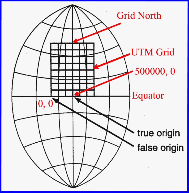
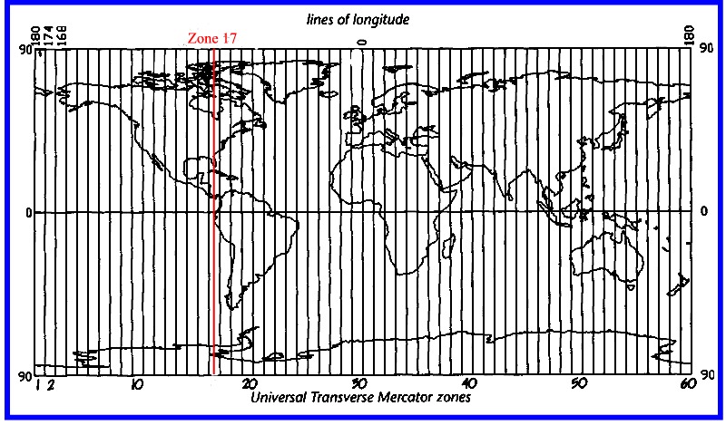
The Universal Transverse Mercator System (UTM) employs a transverse cylindrical method of projection such that distorsion is minimized along a given line of longitude, and a plane orthogonal (rectangular) coordinate system. The Earth is divided into 60 UTM zones each of 6 degrees of longitude, the zones being numbered from west to east, starting a 180W. Sudbury is located close to the centre of zone 17. The line of longitude at the centre of each zone (the central meridian) represents Grid North, and coincides with True North. The N-S lines of the UTM coordinate grid (Eastings) are drawn parallel to Grid North, whereas the E-W lines of the grid (Northings) are drawn parallel to the Equator. The intersection of Grid North with the Equator (the true origin of the zone) is arbitrarily given a coordinate location of 500,000 metres East and 0 meters North, such that a false origin for the grid, that is the point where the numbering sytem is 0 in both axes, is located 500 km west of the true origin. Note that the closer one gets to the zone boundary the larger the angular difference between True North and the UTM N-S grid line. Consequently when plotting dips and strikes of beds measured relative to Magnetic North, it is necessary to correct for this difference. AT Sudbury the difference is only about 10 seconds, and therefore the correction can be disregarded.
LINKS COORDINATE
CONVERSION SOFTWARE
http://mac.usgs.gov/mac/isb/pubs/pubslists/fctsht.html
http://www.ngs.noaa.gov/PC_PROD/pc_prod.shtml#UTMS
http://everest.hunter.cuny.edu/mp/software.html
http://users.skynet.be/tandt/
http://cousin.de/kkisbin/trafo.tcl
PROGRAM UTMS
(Universal Transverse Mercator System)
Programmers: Edward E. Carlson, T. Vincenty
Last Update: 09/26/88; 04/03/90; 12/01/93 Version 2.0
FILE: \AACRSE\LTLG2UTM\UTMS.RTF
1) Go to your folder in
users on Earthnt (H:), where H is the name of the mapped drive Earthnt\Users
on your computer (it could be some letter other than H, or it may not
exist and will have to be created), and make a folder named your initialsltlg2utm
KEEP READING! - (do not include the quotes, and your initials really
means your initials, e.g. wrcltlg2utm, and not the string yourinitials).
If you have not previously used the computers in room 17 and are baffled
by this instruction, do not panic and politely request the help of the
instructor.
Create a window
corresponding to Earthnt\Public\Es505 and copy the folder Earthnt\Public\ES505\ltlg2utm
into the folder you have just created by clicking and dragging the ltlg2utm
folder from the Public window into the Users window.
A: PURPOSE:
To convert NAD 27 or
NAD 83 geodetic positions to NAD 27 or NAD 83 universal transverse
mercator coordinates (UTM) and vice versa.
B: INPUT:
1. The program will compute the UTM coordinates
or geodetic positions interactively or by batch.
a. By entering each geodetic position
or each UTM coordinate.
OR
b. By using a Blue Book file with
geodetic positions, *80* records, following the format given in Appendix
A or a Blue Book file with the state plane coordinates, *81* records, following
the format given in Appendix B.
C: OUTPUT:
EITHER
1. A screen listing.
AND/OR
2. A file with name,
latitude, longitude, northing, easting, zone, convergence, scale factor,
elevation, and geoid height for geodetic positions to UTM coordinates or
a file with name, northing, easting, latitude, longitude and zone number
for UTM coordinates to geodetic positions. Note: the geoid height
value comes from an *84* record following the format in Appendix C. This
record is optional.
AND/OR
3. An output file in
blue book format.
D: EXECUTION:
1. Load the program (UTMS.EXE)
from the floppy disk to the main storage, or the program can be executed
from a floppy disk drive.
2. To execute the program:
a.
Type UTMS or (disk drive name):UTMS (floppy disk).
b.
The program will prompt for:
Whether you want to compute:
I. Geodetic positions to universal transverse mercator coordinates
II. Universal transverse mercator coordinates to geodetic positions.
III. Print the output file on the printer.
Which ellipsoid
do you want: (some sample datums listed)
1. CLARKE
1866
a. NAD27 datum
b. OLD HAWAIIAN datum
c. PUERO RICAN datum
d. GUAM datum
2. GRS80/WGS84
a. NAD83 datum
3. INTERNATIONAL
1910
a.INTR24 datum
4. WGS72
5. OTHER
ELLIPSOID
A. (For requesting
I)
Whether you want to run interactively (Y/N) ?
a. (If answering Yes)
i. Whether you want the output saved in a file ? (If answering Yes)
File Name:
ii. Whether you want an *81* record file ? (If answering Yes)
File Name:
iii. Station name.
iv. Latitude.
v. Direction of latitude
vi. Longitude.
vii. Direction of longitude
b. (If answering No)
i. Name of input file in Blue book format.
(See Appendix A)
ii. Whether you want the output saved in a file ? (If answering Yes)
File Name:
NOTE: To list the output file in the correct format one can use the program
LSTFTN.
Type of coordinate listing ?
Project number ?
iii. Whether you want an *81* record file ? (If answering Yes)
File Name:
B. (For requesting
II)
Whether you want to run interactively (Y/N) ? a. (If answering Yes)
i. Whether you want the output saved in a file ? (If answering Yes)
File Name:
ii. Whether you want an *81* record file ? (If answering Yes)
File Name:
iii. Station name.
iv. Northing.
v. Easting.
vi. Zone number.
b. (If answering No)
i. Name of the input (*81* record) file. (See appendix B)
ii. Name of the output (*80* record) file.
iii. Whether you want the output saved in a file ? (If answering Yes)
File Name:
NOTE: To list the output file in the correct format one can use option
III.
C. (For requesting
III)
i. Name for file to be printed.
NOTE: When computing UMT coordinates from a geodetic
position and then computing a geodetic position using the computed UTM
coordinates the computed geodetic position may not agree with the starting
geodetic position. UTM coordinates are given to only millimeter accuarcy.
Whereas the fifth place in the seconds of the latitude and longitude corresponds
to an accuracy of approximately one tenth of a millimeter.
@ 0 degrees
@ 80 degrees
-5
LATITUDE ( 1.0 X 10 sec)
---> 0.3 mm
0.3 mm
-5
LONGITUDE ( 1.0 X 10 sec)
---> 0.3 mm
0.0 mm
-5
-5
NORTHING ( 0.001 meter)
---> 3.0 X 10 sec
3.0 X 10 sec
-5
-5
EASTING ( 0.001 meter)
---> 3.0 X 10 sec 19.0
x 10 sec
APPENDIX A
Control Point
Record (IE: *80* record) **
CC01-06 Sequence Number
(OPTIONAL)
CC07-10 Data Code (IE: *80*)
CC11-13 Station Serial Number
(OPTIONAL)
CC14 Blank
CC15-44 Station Name
CC45-55 Geodetic Latitude: Deg-Min-Sec,
to 5 decimal places, decimal point implied between CC50-51 (DDMMSSsssss)
CC56 Direction
of Latitude: N or S
CC57-68 Geodetic Longitude: Deg-Min-Sec,
to 5 decimal places, decimal point implied between CC63-64 (DDDMMSSsssss)
CC69 Direction
of Longitude: E or W
CC70-75 Elevation of mark above MSL,
in meters, decimal point implied between CC73-74 (EEEEee) (OPTIONAL)
CC76 Elevation
code
(OPTIONAL)
CC77-78 State or Country Code
(OPTIONAL)
CC79-80 Station Order and Type
(OPTIONAL)
** Format specified in the FGCC publication, Input Formats and specifications of the National Geodetic Survey Data Base.
APPENDIX B
Control Point
Record (*81* record) **
(NOTE: Use
this format for UTMs on the CLARKE 1866, INTERNATIONAL WGS72, and OTHER
ELLIPSOID)
CC01-06 Sequence Number
(OPTIONAL)
CC07-10 Data Code (IE: *81*)
CC11-13 Station Serial Number
(OPTIONAL)
CC14 Blank
CC15-44 Station Name
CC45-54 EASTING, in meters, to three
decimal places, decimal point implied between CC51-52 (XXXXXXXxxx)
CC55-65 NORTHING, in meters, to three
decimal places, decimal point implied between CC62-63 (YYYYYYYYyyy)
CC66-69 UTM - Zone number (0001 -
0060)
CC70-75 Elevation of mark above MSL,
in meters, decimal point implied between CC73-74 (EEEEee)
(OPTIONAL)
CC76 Elevation
code
(OPTIONAL)
CC77-78 State or Country Code
(OPTIONAL)
CC79-80 Station Order and Type
(OPTIONAL)
Control Point
Record (*81* record) **
(NOTE: Use
this format for UTMs on the GRS80/WGS84 ELLIPSOID only)
CC01-06 Sequence Number
(OPTIONAL)
CC07-10 Data Code (IE: *81*)
CC11-13 Station Serial Number
(OPTIONAL)
CC14 Blank
CC15-44 Station Name
CC45-55 NORTHING, in meters, to three
decimal places, decimal point implied between CC52-53 (XXXXXXXXxxx)
CC56-65 EASTING, in meters, to three
decimal places, decimal point implied between CC62-63 (YYYYYYYyyy)
CC66-69 UTM - Zone number (0001 -
0060)
CC70-75 Elevation of mark above MSL,
in meters, decimal point implied between CC73-74 (EEEEee) (OPTIONAL)
CC76 Elevation
code
(OPTIONAL)
CC77-78 State or Country Code
(OPTIONAL)
CC79-80 Station Order and Type
(OPTIONAL)
** Format specified in the FGCC publication, Input Formats and specifications of the National Geodetic Survey Data Base.
APPENDIX C
Geoid Height
Record (*84* record) **
CC01-06 Sequence Number
(OPTIONAL)
CC07-10 Data Code (IE: *84*)
CC11-13 Station Serial Number (must
be the as same as *80* record)
CC15-20 Source
;
(OPTIONAL)
CC21-71 Comments &nb
sp;
(OPTIONAL)
CC72-76 Geoid Height, in meters,
above (positive) or below (negative) the reference ellipsiod, decimal point
implied between CC75-76 (GGGGg)
CC77-80 Sigma
(OPTIONAL)
** Format specified in the FGCC publication, Input
Formats and specifications of the National Geodetic Survey Data Base.