Lec 8: Basic Navigation Concepts
Nighttime Aerial Photography (cf. Assignment 2)
Does it exist?
Announcements
Question re Readings included in Final
Exam...
Ombudsmeeting
The Readings for Today’s Lecture were:
Ch. 14: Compass and Maps
Comments or Questions?
(General, Lab, Assignment, Readings)
Today’s Lecture:
Distance
Raster GIS Operations Clinic
Basic Navigation Concepts (“Part I”)
The Basic Navigation Concepts unit is
based on Chapter 14 “Compass and Maps”
(Appendix D Navigation Instruments
will be covered a bit later)
Distance (“debt”)
Raster GIS Operations Clinic
Non-linear Spread (recap)?
Discussion of:
Clump
Count
(SubScene)
Basic Navigation Concepts
The “Uh, where are we?” problem
(cartoon)
The structure of Chapter 14
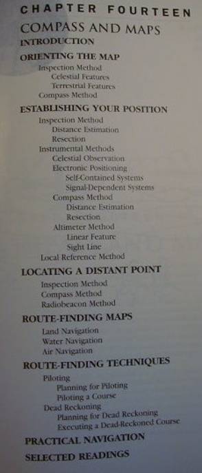
Orienting the Map
What does this mean?...
Inspection method
based on co-visible (or co-sensed)
features
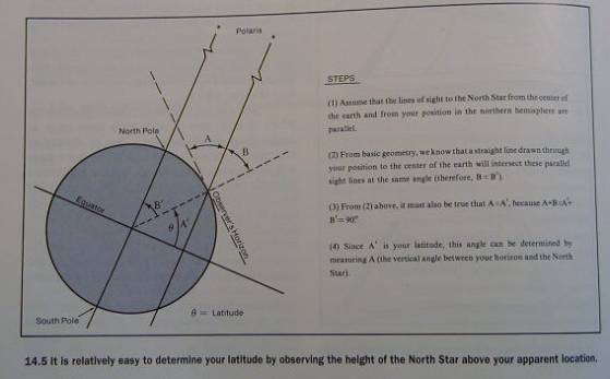
Celestial features
using sun and stars — especially the
North Star
Terrestrial features
One linear feature
Two linear features
Prominent objects
Fig. 14.1
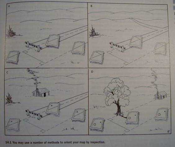
Problem with potential reversal of
orientation (by 180 degrees)
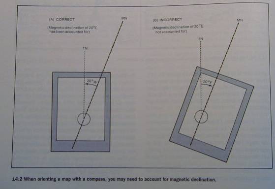
Compass method
Two necessary conditions:
must have a compass
must know the local magnetic
declination
ie. the direction of magnetic north
Fig. 14.2
Establishing Your Position
Three methods
by inspection
by instruments
by local reference
Inspection method
two main inspection techniques:
distance
estimation
resection
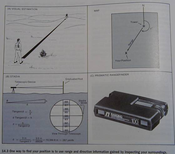
Distance estimation
select a co-visible feature
estimate ground range
convert to map distance (using the map
scale)
mark on map along the proper distance
line
you can double check by using more
than one feature
range finders
stadia and graduated rod
prismatic rangefinder
laser rangefinder (aka Electronic Rulers
or EDMs - Electronic Distance Measurers)
Fig. 14.3
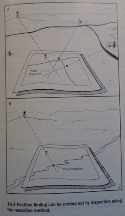
Resection method
this is a less casual and more robust
method
based on
plotting two or three crossing lines
Done by identifying co-visible features
and “raying them in”
these sight lines are drawn using a ruler
and really represent a backsight or back bearing
ideally at least 2 of the lines should
cross at about 90 degrees
note that 3 lines will produce a
useful triangle of error
with only two lines thre’s the
possibility of a hidden error
Fig 14.4
Break
Instrumental methods
Celestial observation
sextant
Q: what doe this thing do and how?...
Fig. 14.5
Electronic positioning
Self-contained systems
require no external information source
a kind of modern-day automated
dead-reckoning system
forms the basis for modern inertial
navigation system (INS)
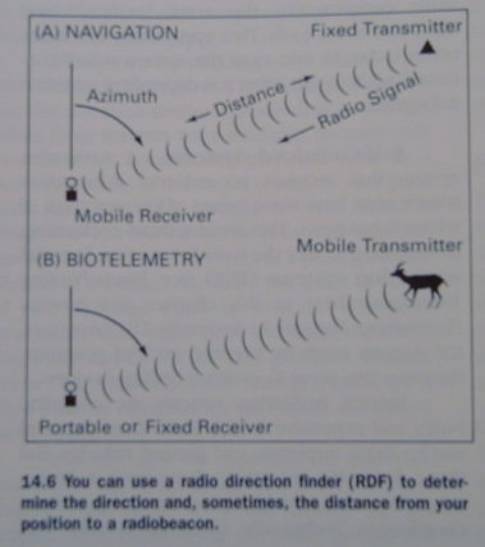
Signal-dependent systems
ground-based radionavigation aids
include passive and active systems
passive reception from one or more radiobeacons
(Rbns)
the receiving unit is called a radio
direction finder (RDF), or radio
compass
Fig. 14.6
active systems
radar (radio detection and ranging)
sonar (sound navigation ranging)
modern systems
GPS (Global Positioning System) to
which the whole next chapter in the text (No. 15) is devoted
GLONASS (GLObal NAvigation Satellite
System)
Compass method
advantages of compass over inspection
method:
a compass can provide a more accurate
direction
no need to orient the map to the north
as with the inspection method, there
are two ways to work with a compass to establish position:
Distance estimation
Resection
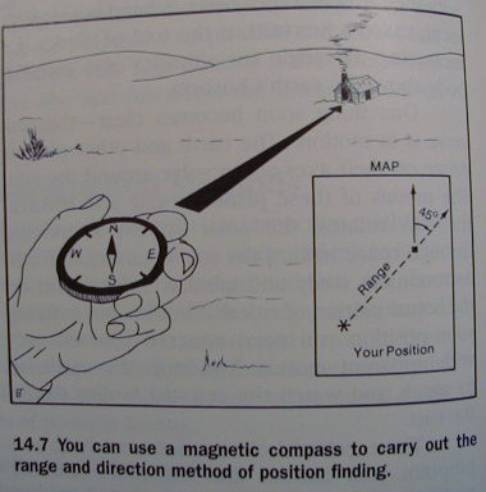
Distance estimation
use the compass to get a bearing to a
feature
estimate the distance (using the
previously described methods)
convert to map distance (using the
map’s scale)
plot it on the map
Fig. 14.7
Resection
same as resection method under the
inspection technique, but this time with the aid of a compass,
no need for a sight-rule (alidade) or
a straight-edge (for ‘aiming’ and plotting)
use a protractor to plot the bearing
Fig. 14.8
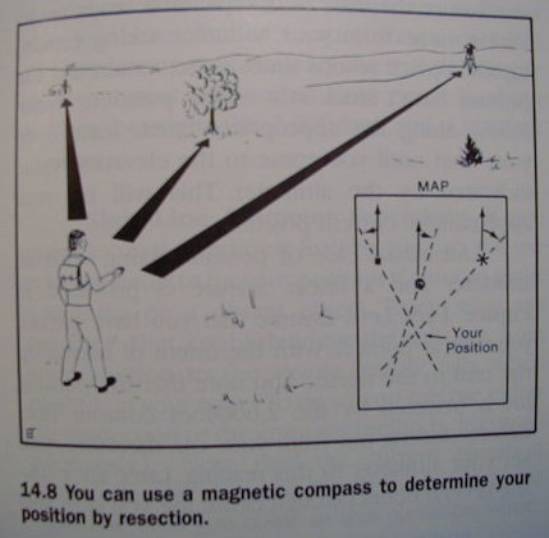
use two or three points (as before)
if you only have two points, or if you
have three but want high accuracy),
then repeat the
measurements (eg. twice)
and get a
‘point-cluster error’ instead of an error triangle
*********************
Altimeter method
These guys (altimeters) become
particularly useful in mountain environments
where the position is defined by
[X,Y,Z], it helps having Z info in order to figure out the position [X,Y]
Equiped with topo map (has contour
lines) and pocket altimeter, only one ground feature is sufficient to get a
position fix
linear features are particulary useful
(know as ‘handrails’ in the science/art/sport of orienteering)
Barometric altimeters need to be
calibrated
Q:
how and when is this done?
Q:
What other kind of altimeters are there?
Linear feature altimeter procedure
Fig. 14.9
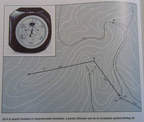
Sight line altimeter procedure
first establish sight line to a distant object and plot it
read altimeter elevation
follow sight line until it ‘hits’ the
correct elevation
Fig. 14.9 also shows this method
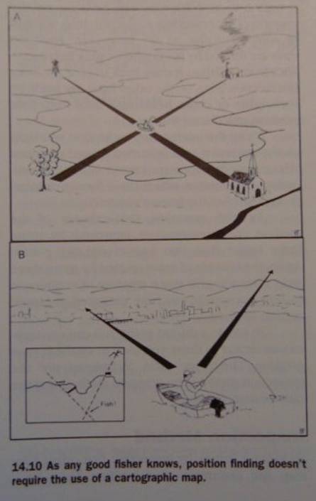
Local reference method
when there are no aids (including) map
and high precision isn’t required
the fisher’s solution
locate two pairs of features on
opposite sides of the lake
wide angle, eg.
45 degrees
or better still, line up two pairs of features along one
shoreline
in effect this amounts to crossed
backsights (and thus is a type of resection)
Fig. 14.10
‘til next week!